Plant Monitor Prototype Update
Date: 2025-01-24
Last Updated: 2025-10-10
My Wireless Plant Monitor! (Prototype)
I just wanted to do a quick write-up on a side project I'm working on and share photos of an early prototype.
What is it:
- I am working on an IoT system to monitor my plants and let me know when they need water.
How does it work
Hardware
- Raspberry Pi Pico W
- Core Electronics Capacitive Soil Moisture Meter
- Core Electronics Pico Timer
- A couple of AA batteries
Software: - The firmware on the Pico is running MicroPython — a small-footprint port of Python designed to run on embedded devices.
- It shoots messages to my main PC via MQTT.
- My PC receives the messages via Mosquitto (MQTT broker) running locally.
- It then stores the messages in a SQLite database.
- A Python Flask app pulls out the data and displays it on a web dashboard.
- (The web dashboard is hand-rolled HTML, CSS, and vanilla JS.)
Why not just...
Why not just buy something, use an existing framework, check my plants myself, do literally anything else with my time.
Because I wanted to build something myself, and see how it works.
2 Requirements
I wanted my device to have the following characteristics
- Communicate wirelessly.
- Scalable
- I have a few plants in a bunch of different places. This means I will need a number of sensors.
- This implied several sub-requirements
- Cost
- The device should cost less than $30 AUD per unit.
- Software Scalability
- The dashboard should scale to support up to 10 clients.
- Manufacturability
- I should be able to assemble future units in less than 30 minutes per unit (not including 3D print time).
- Cost
- Power:
- The device should last at least a month on a set of batteries.
- The device should be powered by disposable alkaline batteries (this is personal preference for convenience, safety, and scalability).
3 How I built it
3.1 Getting the electronics and sensors working
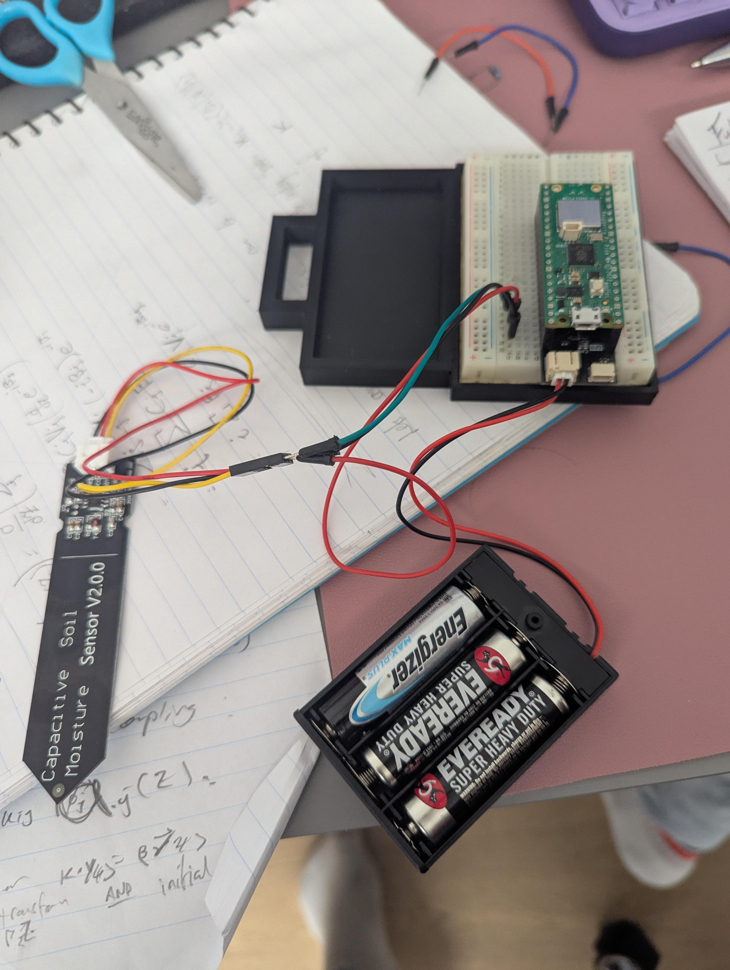
The first step was to get the physical bits and bobs working and playing nicely together. I threw all the components on a breadboard, plugged the sensor into my microcontroller's ADC, wrote a basic script to print the reading to serial and shut down. Then I tested it on USB power, and then on battery power using the timer. Easy!
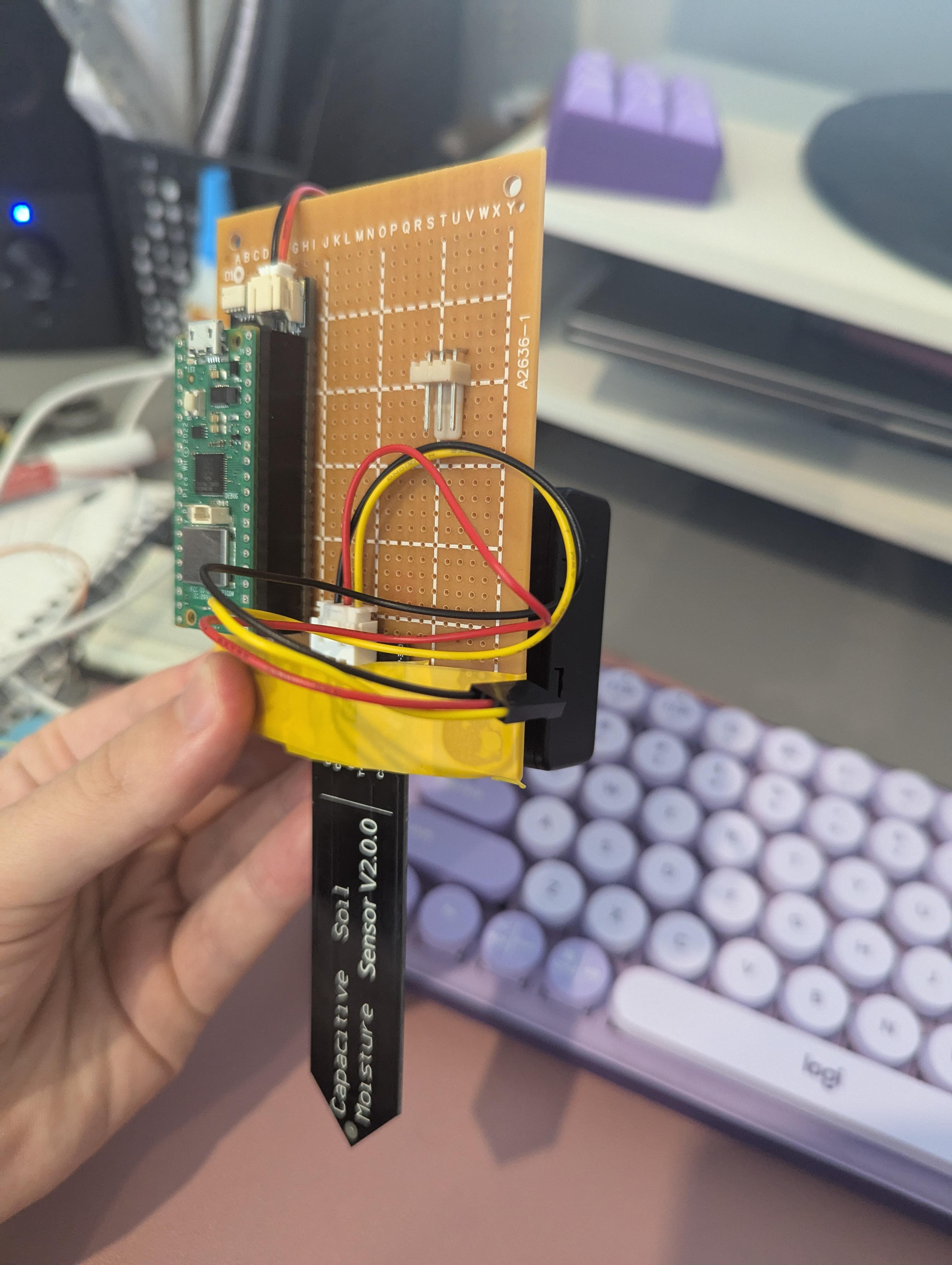
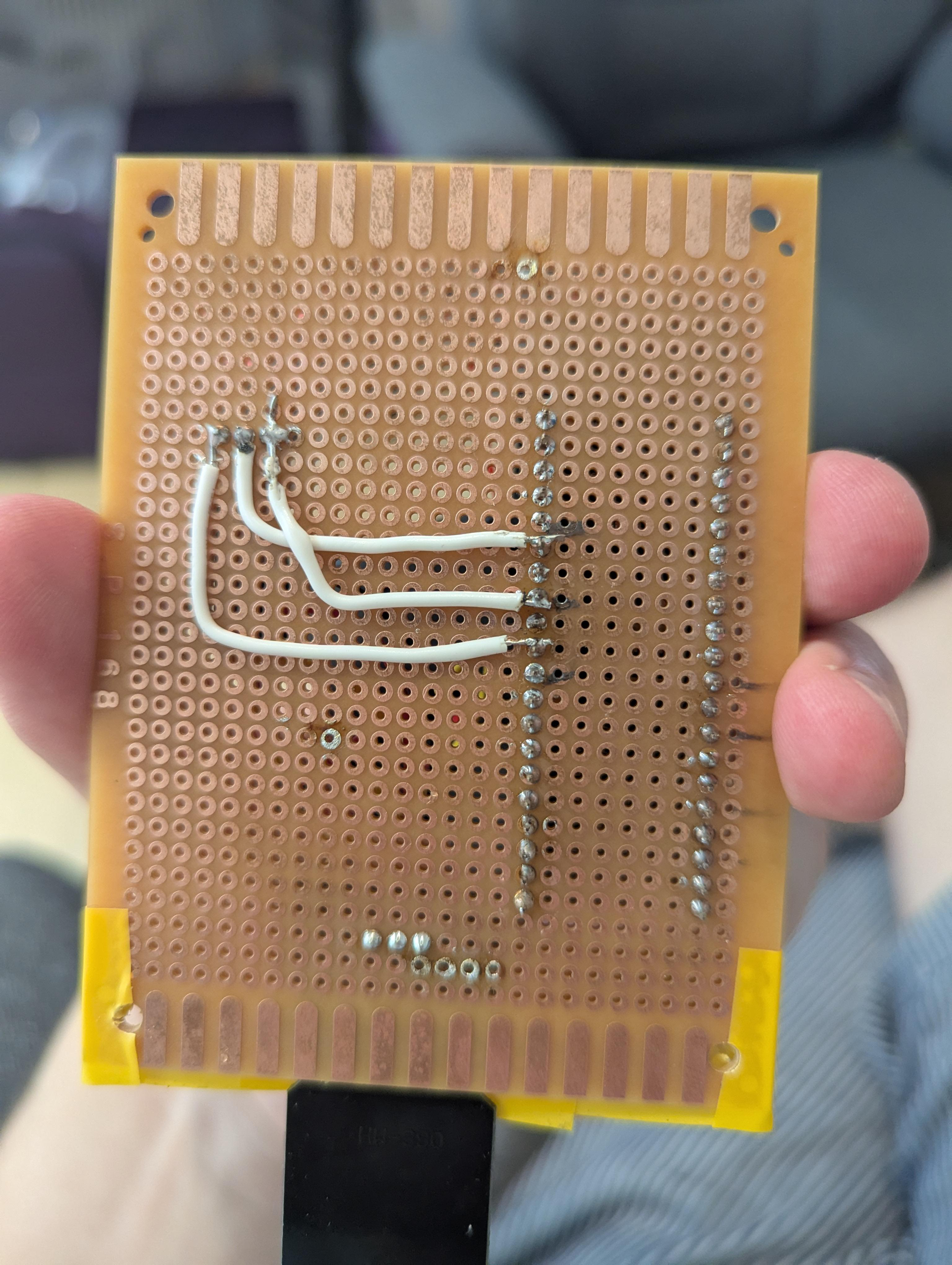
3.2 Soldering it all in place
Once I was happy that the electronics worked, I found a leftover soldered breadboard from some previous work and soldered everything down. I also found an old three-pin connector, which was lucky — this meant I could swap out the sensor in case I broke it or something.
3.3 Write the firmware
Next up, I had to do a second pass at the firmware and get it actually doing what it was meant to. I got the device to:
- Connect to Wi‑Fi.
- Take five readings (and average them).
- Scale the reading to a calibrated value.
- Send it over Wi‑Fi to the base.
- Shut down.
Here is where I ran into problems: For some reason, there was a bug that showed up only when the USB was not plugged in. This was a nightmare to debug. Eventually I hooked up an extra OLED display over I2C just to print out debug statements.
Eventually I figured out the problem and was able to move on. For those curious: I had the device set to restart every 6 seconds. For reasons still unknown, the device could connect to the Wi‑Fi and take its reading in this time on USB power, but it took longer than 6 seconds on battery power, so the restart signal would hit halfway through connecting to the Wi‑Fi and everything would fail. Solution: restart on a one-minute cycle instead of 6 seconds.
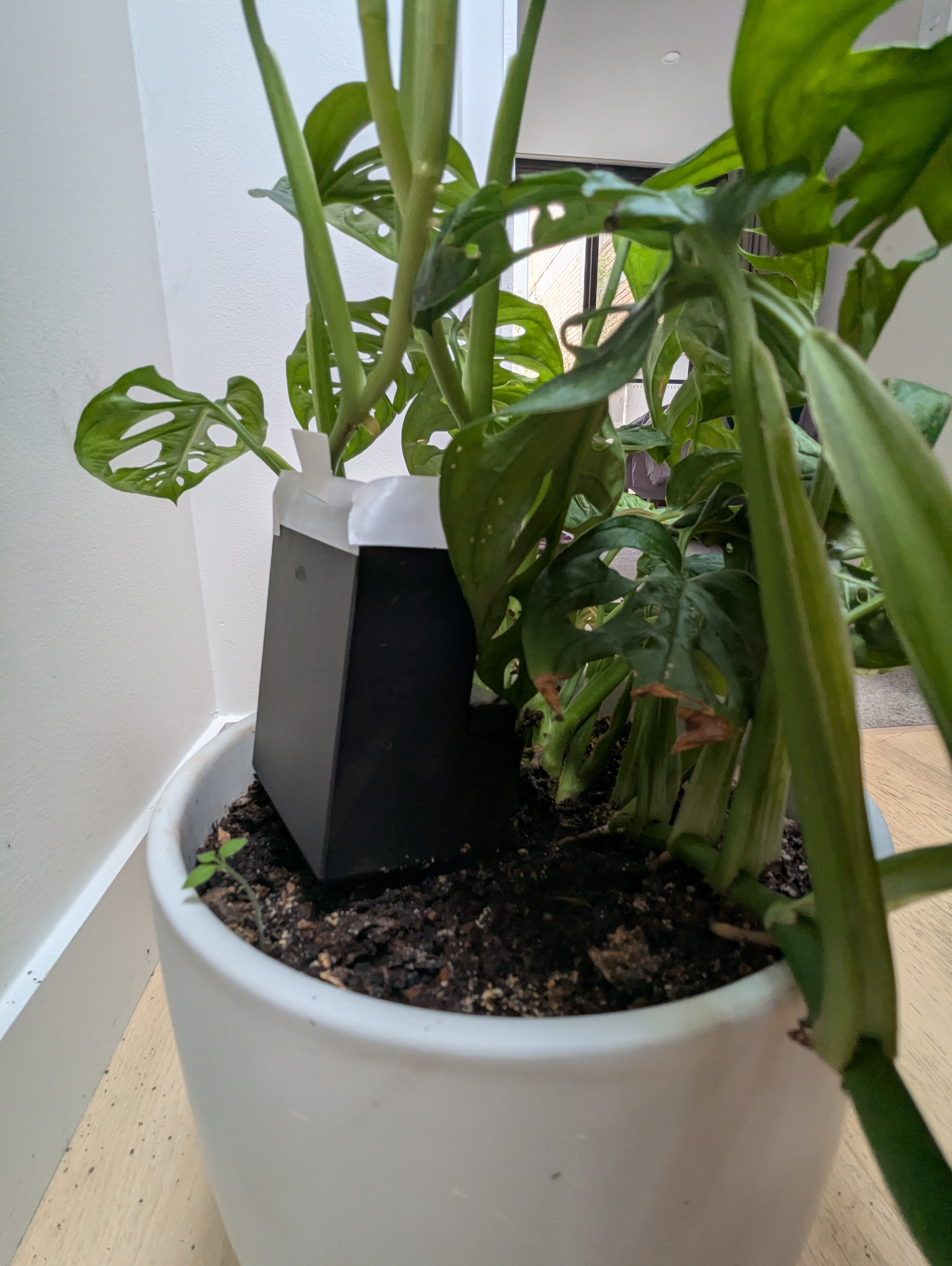
- 3D print a case
It isn't pretty, and I'm not sure it is waterproof, but here is the case for prototype 1.

3.4 Write the server code
Now comes the bit that I'm sure most people think is the easy part, but I find tedious. I needed to write the Python code to:
- Catch the incoming MQTT messages.
- Chuck them into a database.
- Start a web server.
- Grab all the data from the database.
- Make it look pretty.
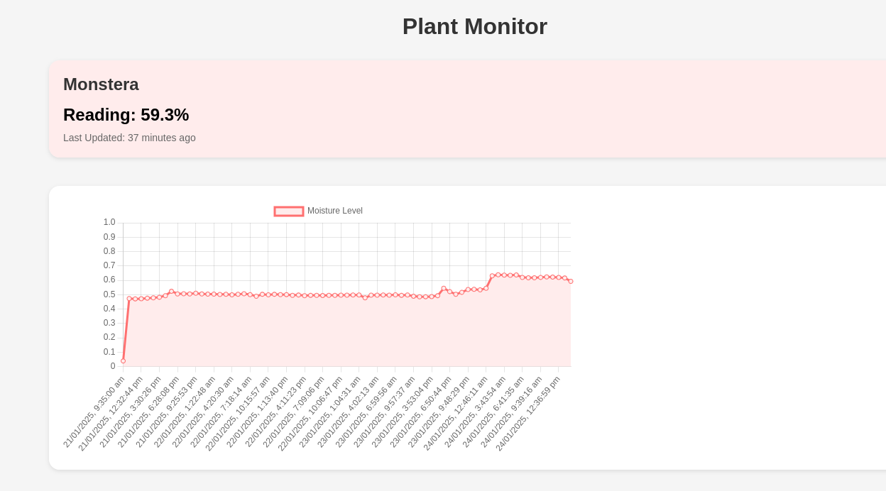
This is what I ended up with!
4 Improvements for V2
I am sharing the current state of the project, but I wouldn't recommend copying it just yet (at least without a lot of modification). Here is how I plan on improving V2
4.1 Device housing and footprint design
- The housing of the device is god-awful. It is way clunkier than the parts it is made of.
- It isn't watertight (I just avoid hitting it when I water the plants).
- The batteries aren't even enclosed.
- The design of the case is a little funny: the switch and the battery replacement hatch are on opposite sides of the box, so I couldn't quite figure out how to enclose it and keep both accessible.
4.2 Electronics
- I plan on trying to see if I can reduce the power requirement to a pair of AA batteries, instead of three.
- This will help reduce the footprint of the system
4.3 Server Code
- At the moment the web page looks very ugly: the graph is reactive which is nice, but the scale on the x-axis isn't working properly and is evenly spacing each measurement regardless of measurement time.
- This should be easy to fix, but it requires me to learn a bit more JavaScript.
- I would like to deploy the whole thing inside a Docker container.
4.4 Documentation
- Now that I have spotted the mistakes in V1 and know what improvements I want in V2,
- Version 2 will be properly documented, including:
- Bill of Materials (BOM)
- Documented firmware and server software, including install instructions for the server
- 3D manufacturing files for the case (e.g., .stl, .3mf, as well as design files)
- Photographed assembly instructions.